

(Click images for larger version)
Note: I occasionally get comments questioning the safety of the exposed wires, so I'll clarify one point: This clock is powered from an external "wall-wart" transfomer; there is no more than 12V on any exposed conductor.
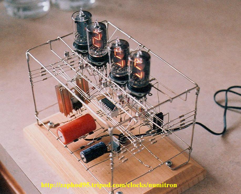
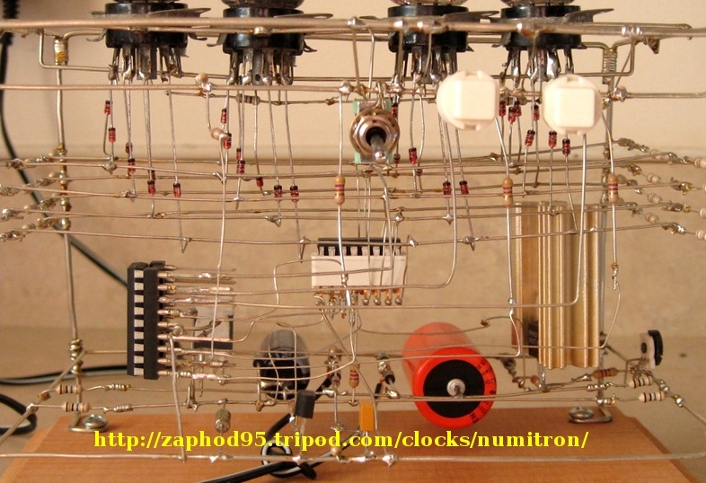
The structure is busbar wire of various gauges, formed and soldered into place. The outer frame is grounded; the inner "live" conductors are supported by 10-Megohm resistors which serve as "insulators." At 5V, 10MΩ introduces only 500nA of leakage; not a problem for a low-frequency low-impedance application like this.
The displays are DR2000 Numitron tubes. They're driven in a multiplex arrangement; with filament displays this requires a diode in series with each filament, seen below the tubes. Segments are driven by a UCN5891 lamp driver (its serial input conserves MCU pins), digits are driven by the four 2N2222A transistors visible just below and in front of the tubes.
Power is provided by a 12VAC wall transformer. A Microchip PIC16F628 keeps the time by dividing the 60Hz power line frequency. An LM340T5 regulates MCU power, while an LM317T regulates the display voltage at 8V. With the multiplex drive, each digit receives an 8Vpk squarewave with a 25% duty cycle. This equates to 4V RMS, just below the tubes' normal 5V operating voltage.
The information in this page is provided for general interest of hobbyists, collectors, etc. The author reserves all rights under copyright or any other relevant intellectual property laws; permission is not granted to duplicate this design for sale or other commercial purposes. This also applies to comments under the "Possible Variations" section below.
LED displays instead of Numitrons:
Numitrons are getting scarce. LED 7-segment displays, however, are
abundant and inexpensive. The same novel open-frame appearance would be
retained, with little or no change to the software or hardware.
BCD readout:
Another layer of novelty could be added by using a BCD readout instead
of 7-segment displays, with coulumns of four lamps representing each
decimal digit, such as this clock. Or even
decimal readout, with columns of nine or ten lamps. Lamps could be
incandescent or LED.
The usual digital clock stuff:
There is still room in the microcontroller's program memory for adding
features commonly found in digital clocks, such as a calendar or alarm
clock. Two more digits could be added to display the seconds count.
Nixie, plasma, or vacuum-flourescent displays:
Probably not advisable as-is; 180V or more would be present on exposed
wires in the case of cold-cathode tubes; even VFDs often requre 30V or
more. However, such a clock might be enclosed in clear plastic or glass.