
(click image for larger version)
The construction is fairly simple; the LEDs are arranged in a 4x4 matrix, driven by a ULN2803 lamp driver (the red LEDs require 40mA peak; too much for the MCU to drive directly). Four of the ULN2803's eight outputs drive the cathodes, and the other four drive 2N2907 transistors, forming level-shifters to drive the anodes. A microchip PIC16F628 keeps the time, based on a 4.9152MHz oscillator module. Power comes from a 12VDC wall transformer, with a 9V backup battery.
This is the first time I've tried using a crystal oscillator module as a clock timebase. They are very easy to use, but tend to lack the precision necessary for a clock. To compensate for this, the time is trimmed in software: Once every hour, a "leap-second" is taken; that one second is lengthened or shortened by a constant value, calculated after running the clock for several weeks. In this version, changing the leap-second constant requires re-compiling the program; I may re-write the code to use the MCU's internal data EEPROM, so trimming doesn't require dissasembling the clock and removing the MCU.
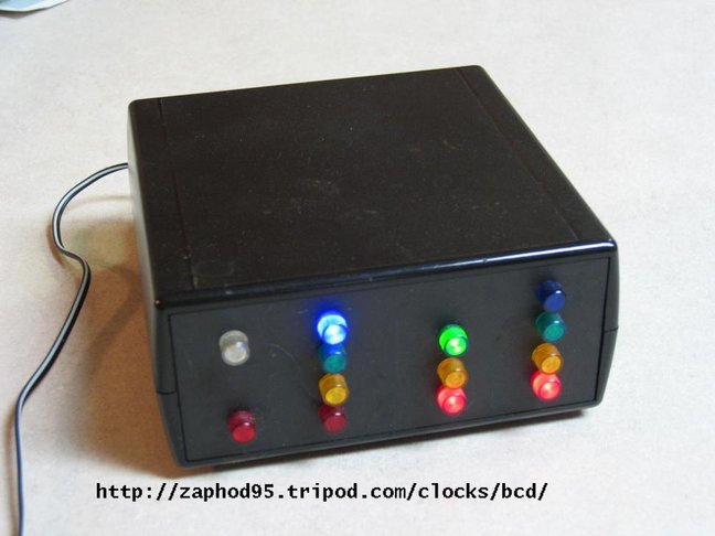
One minor drawback is that a zero is indicated by no lamps lit. This is true BCD, but is hard to read in dim light; is the time 10:01 or 10:10? I've thought about modifying the display subroutine so all lamps glow dimly (by duty-cycle modulation) as place-holders for otherwise unlit digits.
I've also thought about building another version, with two more columns for a seconds display, or possibly combining the BCD readout with the construction technique of my open-frame clock project.