
(click image for larger version)
For those familiar with electronics, a more technical description of the clock can be found here. What follows is my attempt at a non-technical guided tour:
Looking at the interior photo, the Integrated Circuit (IC) in the center, near the far end of the board, is the brains of the system. It's a microcontroller; essentially a small microprocessor system that can be programmed to do various tasks, often with very few external components.
The IC to the left of the microcontroller is generally called a "lamp driver array;" in general terms it's basically a simple amplifier module. It's necessary because, in this application, the display lamps require more current than the microcontroller can produce by itself.
To the right is a crystal oscillator module, in the rectangular metal case. This generates a precision timing signal, which the microcontroller uses as a reference to measure time.
The IC in the lower right is a voltage regulator. It and the few components near it clean up the power for the microcontroller.
Just barely visible on the right edge of the photo is a 9-volt battery. This is a back-up power supply to keep the clock running in the event of a power failure. It also gives an idea of scale; the board that the electronics are mounted on is approximately 3" x 4" (75mm x 100mm).
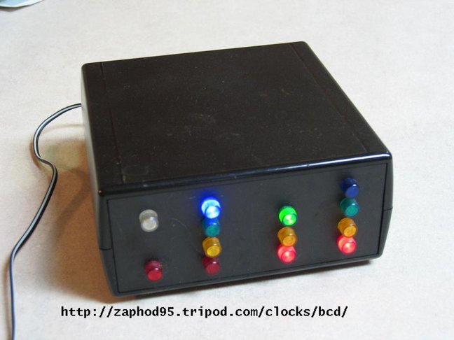
So, what's with the rows of lights? This particular clock uses a Binary-Coded Decimal readout. BCD is one way of storing numbers in computer systems; not very efficient for complex math, but well-suited to simple stuff like counting time of day, and not really that hard for a human to read, with a little practice:
Each column of lamps is one digit of the time. Within each column, each lamp has a value, based on its height in the column; starting from the bottom, the red lamp is 1, yellow is 2, green is 4, and blue is 8. Add the values of the lit lamps in each column. So, in the left photo, the time shown is 8:51. The white lamp is a "PM" indicator.